 README
README
Reverse Engineering remote control Electric Radiators
The radiators in my apartment are electric and remotely controlled by battery powered devices mounted nearby on the wall.
This setup is not supported by any of the popular home thermostats so I decided to build my own control system.
Understanding the RF controllers
Each controller is mounted on the wall and has a display showing the current temperature and has buttons for configuring the target temperature. One controller can be paired to multiple radiators which will receive the same settings whenever the controller sends an update.
There is no documentation, as far as I know, as to the protocol, frequency, modulation, etc.
Discovering the frequency
Following a guide by someone reverse engineering their home alarm I managed to pinpoint the frequency of the communications using SDR# and an RTL SDR.
Capturing a packet
At this point I disassembled a broken remote control in the hope that it would enlighten me some more as to the protocol and modulation. Inside I found a TI CC1100, similar to in the other reverse engineering article!
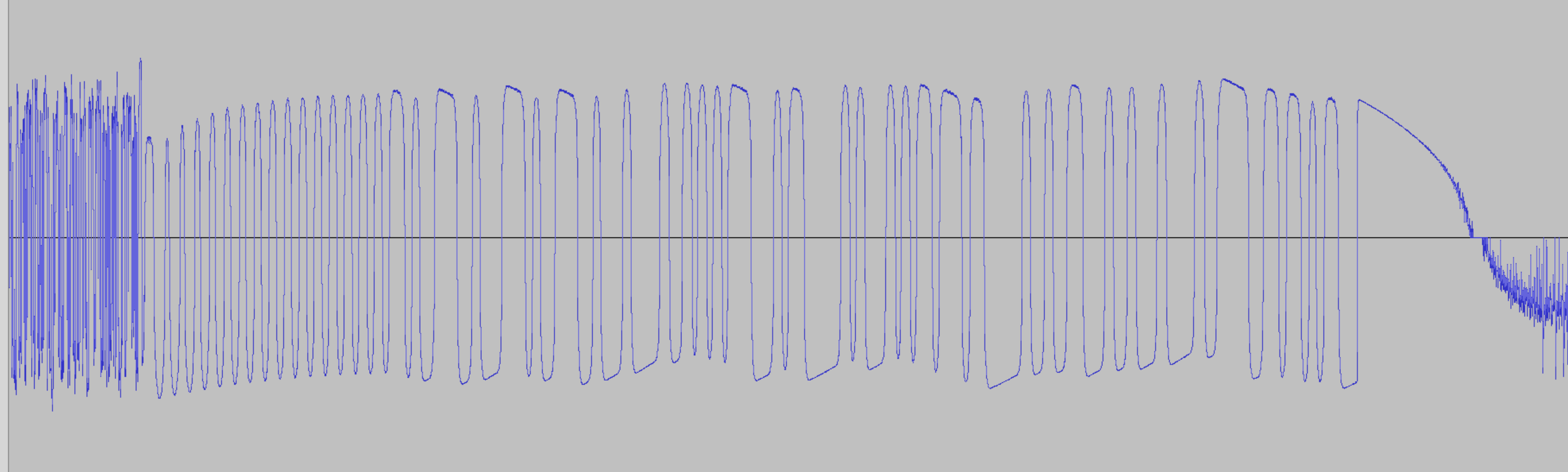
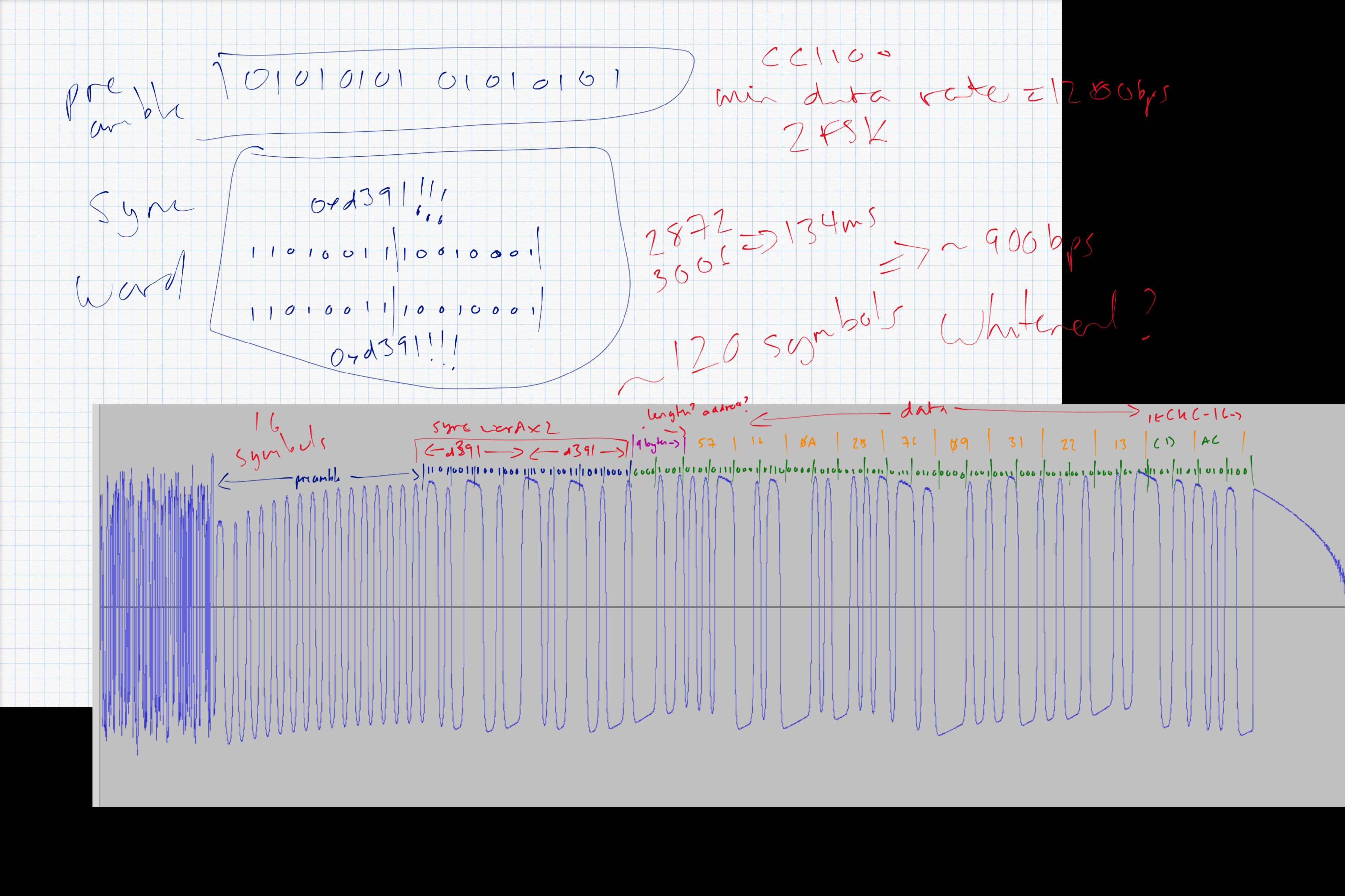
From here I played around with GNURadio until I managed to capture and demodulate (2-FSK) the signal and save the waveform.
Decoding the packet
I struggled to get GNURadio to fully decode the packet so I opened the waveform in Audacity and tried to decode it by hand. It was tedious work but it was fairly easy to separate the waveform into the different parts of the packet as documented by TI:
- Preamble: 16 bits alternating high/low
- Sync Word: An arbitrarily chosen 16 bit word
- Length: 1 single byte packet length indicator (not including CRC)
- Data: 9 bytes of data
- CRC: 2 bytes of CRC
At this point I was clearly on the right track as the sync word came out as 0xd391, the same as the other blog and also the default sync word for the CC1101
(clearly, the developers were lazy on both products).
Building a receiver
So now we know the rough parameters of the signal and the packet format:
| Frequency | 868.3MHz |
| Deviation | 40KHz |
| Modulation | 2-FSK |
With this we should be able to receive packets.
Initially I tried to get this to work with GNURadio but gave up and discovered that you can buy a CC1101 (the successor to the CC1100) on a board on ebay for a few bucks. The first one I ordered turned out to be configured for 433MHz and it turns out the RF filter is different between a 433MHz and an 868MHz board.
On receiving an 868MHz CC1101 I hooked it up to an Arduino and started playing around but it was behaving weirdly and I gave up.
A while later it occurred to me that the voltage levels on a standard Arduino Uno are 5V and the CC1101 expects 3.3V!
From here I connected it to a Raspberry Pi Zero W (which has 3.3V levels). To add to the fun I decided to try to interface with the CC1101 using go after discovering the EMBD framework. This makes interfacing with SPI and I2C and so on relatively easy and with a much nicer development environment than the generally awful Arduino code lying around the web.
A working CC1101
After some hacking around there was great rejoicing at the point where I could read the PARTNUM and VERSION registers
from the CC1101 over SPI and see that they matched the expected values from the datasheet.
From here I could more or less fully control the CC1101 to do what I wanted. Unfortunately, the values for the frequency configuration registers are fairly opaque. The only real way to configure them is to download TI's SmartRF Studio. This GUI tool lets you configure the CC1101 registers and then export the values to a file. The nice part is that it lets you write your own template for exporting the register values so it was trivial to generate a file of go constants for my guessed settings.
Receiving Packets
Now my CC1101 was configured correctly and when set to receive mode, I would actually see packets arriving. I could see packets that correlated well with one of the remote controls sending a packet but sadly there was also a lot of other junk.
After digging through the datasheet I discovered it is possible to make the CC1101 only interrupt when it receives a full packet with a valid CRC. Configuring this option suddenly cleared all the chaff and I could see just the packets that were good candidates for being from a controller.
Decoding Packets
So now I could see packets arriving. From here, I tried each remote in turn and each setting on a single remote in turn and documented the packets generated.
From inspection it was easy to see that the packet format was roughly:
| 0x0 | 0x1 | 0x2 | 0x3 | 0x4 | 0x5 | 0x6 | 0x7 | 0x8 |
|---|---|---|---|---|---|---|---|---|
| IDENT2 | IDENT1 | IDENT0 | ADDR1 | ADDR0 | MODE | DAYTEMP | NIGHTTEMP | DEFROSTTEMP |
The first 3 bytes are some unique identifier so the system knows these packets are for it (they probably should have just set a unique sync word and let the CC1101 do the hard work). The next 2 bytes are the target address of a radiator. The next byte is the mode that the radiator should change to (day, night, defrost or off). The last 3 bytes are the target temperatures in degrees Celsius for each mode multiplied by two (so it can represent half degrees).
Sending Packets
So now we understand and can follow the packets flying around my apartment. The next step is being able to send our own packets so we can replace the remote controls.
With only a small amount more code it was simple to start sending identical packets via the CC1101. The only hiccup was that occasionally a radiator would miss a packet. This was easily solved by just transmitting each packet three times as they are idempotent.
More Work
An unfortunate part of this protocol is that, while the remote controls can display the current room temperature, they do not transmit it at any point. So, in order to build an automated thermostat I needed to record the temperature some other way.
After a little research, I stumbled upon the SHT3x series of temperature and humidity sensors.
These sensors work using I2C so it ended up being simple to interface with one from both a Raspberry Pi using EMBD and an Arduino using the builtin I2C library.
The final steps will be combining a CC1101, a SHT3x and an Arduino Pro Mini to try to create a low power (coin battery for ~1 year) wireless temperature sensor to complement the remote control of the radiators.
 Documentation
Documentation
Index 
- Constants
- type CC1101
- func (c *CC1101) Close()
- func (c *CC1101) FlushRx()
- func (c *CC1101) Init() error
- func (c *CC1101) ReadBurst(address byte, num byte) ([]byte, error)
- func (cc1101 *CC1101) ReadSingleByte(address byte) (byte, error)
- func (c *CC1101) Receive() ([]byte, error)
- func (cc1101 *CC1101) Reset() error
- func (cc1101 *CC1101) SelfTest() error
- func (c *CC1101) Send(packet []byte) error
- func (c *CC1101) SetIdle() error
- func (c *CC1101) SetRx() error
- func (c *CC1101) SetState(state byte) error
- func (cc1101 *CC1101) SetSyncWord(word uint16) error
- func (c *CC1101) SetTx() error
- func (cc1101 *CC1101) Strobe(address byte) (byte, error)
- func (c *CC1101) WriteBurst(address byte, data []byte) error
- func (cc1101 *CC1101) WriteSingleByte(address byte, in byte) error
Constants 
const (
	// Read/write flags.
	WRITE_SINGLE_BYTE = 0x00
	WRITE_BURST       = 0x40
	READ_SINGLE_BYTE  = 0x80
	READ_BURST        = 0xc0

	BYTES_IN_RXFIFO = 0x7f
	RXFIFO          = 0x3f
	TXFIFO          = 0x3f
	OVERFLOW        = 0x80

	// Bitmask for reading state out of chip status byte.
	STATE = 0x70

	CRC_OK      = 0x80
	RSSI        = 0
	LQI         = 1
	RSSI_OFFSET = 74

	// Strobes
	SRES  = 0x30 // Reset
	SRX   = 0x34 // Set receive mode
	STX   = 0x35 // Set transmit mode
	SIDLE = 0x36
	SFRX  = 0x3a // Flush RX FIFO buffer
	SFTX  = 0x3b // Flush TX FIFO buffer
	SNOP  = 0x3d

	// Status Registers
	PARTNUM = 0xf0
	VERSION = 0xf1
	RXBYTES = 0x3b

	// Config Registers
	IOCFG2 = 0x00
	IOCFG1 = 0x01
	IOCFG0 = 0x02

	FIFOTHR = 0x03

	SYNC1 = 0x04
	SYNC0 = 0x05

	PKTLEN   = 0x06
	PKTCTRL1 = 0x07
	PKTCTRL0 = 0x08

	ADDR = 0x09

	CHANNR  = 0x0a
	FSCTRL1 = 0x0b
	FSCTRL0 = 0x0c

	FREQ2 = 0x0d
	FREQ1 = 0x0e
	FREQ0 = 0x0f

	MDMCFG4 = 0x10
	MDMCFG3 = 0x11
	MDMCFG2 = 0x12
	MDMCFG1 = 0x13
	MDMCFG0 = 0x14

	DEVIATN = 0x15

	MCSM2 = 0x16
	MCSM1 = 0x17
	MCSM0 = 0x18

	FOCCFG = 0x19
	BSCFG  = 0x1a

	AGCCTRL2 = 0x1b
	AGCCTRL1 = 0x1c
	AGCCTRL0 = 0x1d

	WOREVT1 = 0x1e
	WOREVT0 = 0x1f
	WORCTRL = 0x20

	FREND1 = 0x21
	FREND0 = 0x22

	FSCAL3 = 0x23
	FSCAL2 = 0x24
	FSCAL1 = 0x25
	FSCAL0 = 0x26

	RCCTRL1 = 0x27
	RCCTRL0 = 0x28

	FSTEST  = 0x29
	PTEST   = 0x2a
	AGCTEST = 0x2b
	TEST2   = 0x2c
	TEST1   = 0x2d
	TEST0   = 0x2e
)
Variables 
This section is empty.
Functions 
This section is empty.
Types 
type CC1101 
type CC1101 struct {
	// contains filtered or unexported fields
}
func (*CC1101) SetSyncWord 
 Directories
Directories
| Path | Synopsis |
|---|---|
|
Package control is a generated protocol buffer package.
|
Package control is a generated protocol buffer package. |
|
status
|
|